

TI SAE J1772 compatible electric vehicle charger r
TI公司的TIDA-010071是SAE J1772兼容的电动汽车服务管理设备(EVSE)参考设计,用于Level 1和Level 2级EV充电器.电动汽车服务管理设备(EVSE)从电网给电动汽车(EV)提供安全的电源.EVSE控制系统包括辅助电源,离板的AC/DC大功率电源(仅在DC充电站),能量计量单元,AC和DC剩余电流探测器,隔离监视器单元,带驱动的继电器和接触器,单线双向通信,服务和用户接口.该参考设计具有超低待机隔离的AC/DC辅助电源,紧接转换器和线性稳压器,基于比较器的控制导向接口,以满足SAE J1772标准,以及一个有效继电器和接触器驱动, 以及继电器和接触器上的隔离线电压检测.主要用于AC充电(桩)站和DC充电(桩)站.本文介绍了参考设计TIDA-010071主要特性,AC Level 1和Level 2系统配置图和设计系统主要指标,框图,电路图,材料清单和PCB设计图.
SAE J1772-compliant electric vehicle service equipment reference design for level 1 and 2 EV charger Electric vehicle service equipment (EVSE) facilitatespower delivery to electric vehicles safely from the grid.An EVSE control system consists of an auxiliary powerstage, an off-board AC/DC high power stage (only inDC charging stations), energy metering unit, AC andDC residual current detector, an isolation monitor unit,relays and contactors with drive, two-waycommunication over single wire, and service and userinterfaces. This reference design highlights an ultralowstandby isolated AC/DC auxiliary power stagefollowed by converters and linear regulators, acomparator-based control pilot interface to meet theSAE J1772 standard, an efficient relay and contactordrive, and isolated line voltage sensing across therelay and contactor.
参考设计TIDA-010071主要特性:
• Ultra-low standby UCC28740-based isolatedAC/DC stage to achieve ENERGY STAR®certification for EV charging stations
• Tight output voltage regulation (< ±5%) of LDOsand the high slew rate of the TLV1805 deviceensures SAE J1772 certification for the control pilotinterface
• Ultra-low standby as well as cost-optimizedconverters and linear regulators to power up points-of-load
• DRV110 current controller to drive high-currentrelays and contactors for thermal protection andreducing power dissipation
• Isolated line voltage sensing using the ISO1212digital-input receiver for welded relay and contactordetection
参考设计TIDA-010071应用:
AC charging (pile) station
DC charging (pile) station
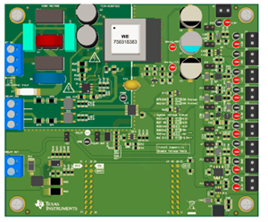
图1.参考设计TIDA-010071外形图
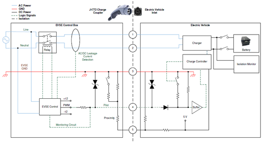
图2.AC Level 1和Level 2系统配置图
系统主要指标:
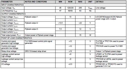
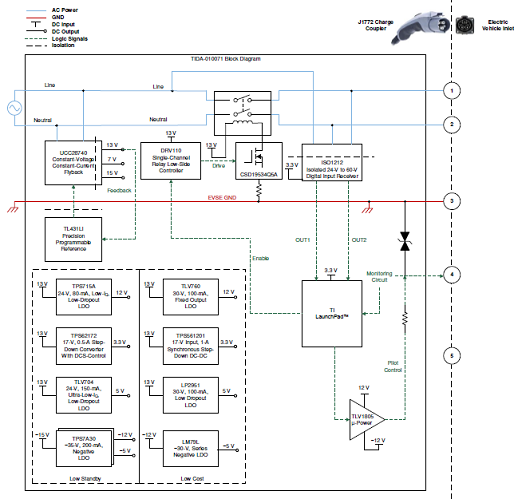
图3.参考设计TIDA-010071框图
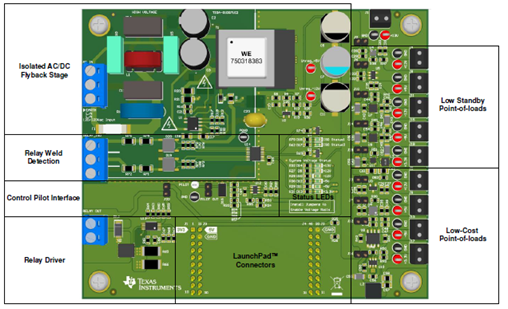
图4.参考设计TIDA-010071 PCB顶层图
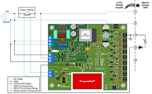
图5.外接元件和参考设计TIDA-010071的连接图
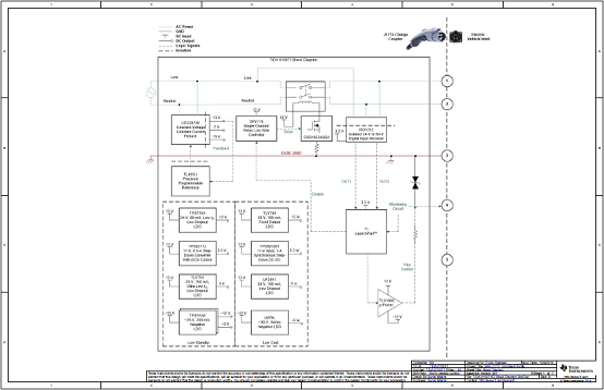
图6.参考设计TIDA-010071电路图(1)
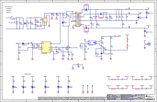
图7.参考设计TIDA-010071电路图(2)
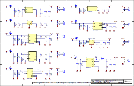
图8.参考设计TIDA-010071电路图(3)
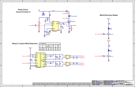
图9.参考设计TIDA-010071电路图(4)
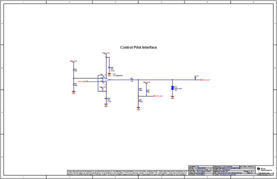
图10.参考设计TIDA-010071电路图(5)
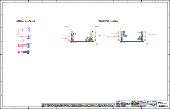
图11.参考设计TIDA-010071电路图(6)
参考设计TIDA-010071材料清单:
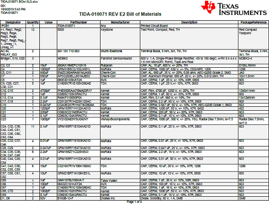
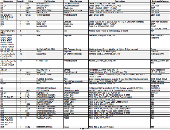
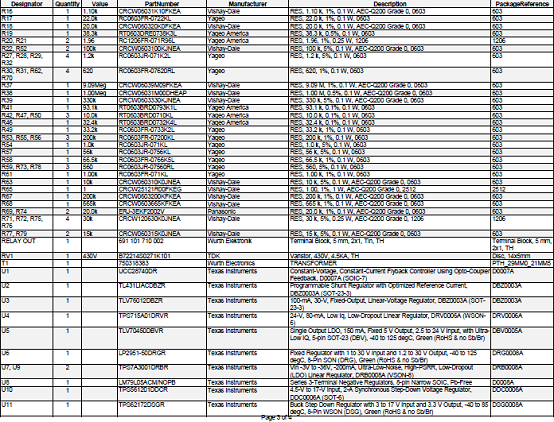
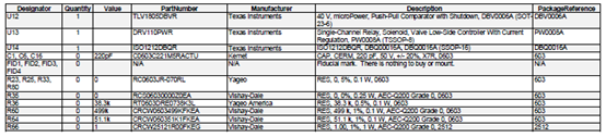
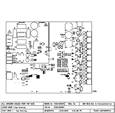
图12.参考设计TIDA-010071 PCB设计图(1)
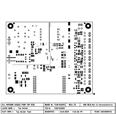
图13.参考设计TIDA-010071 PCB设计图(2)
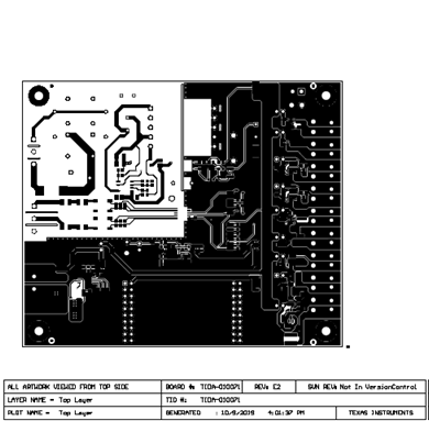
图14.参考设计TIDA-010071 PCB设计图(3)
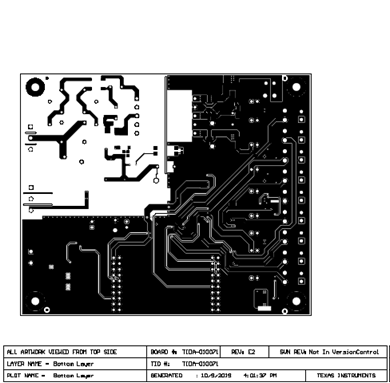
图15.参考设计TIDA-010071 PCB设计图(4)
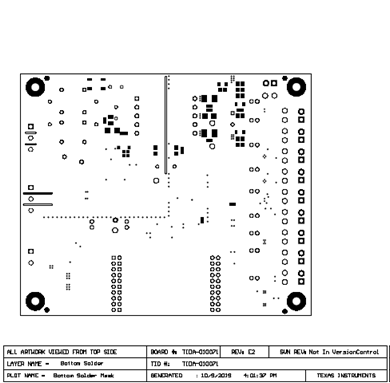
图16.参考设计TIDA-010071 PCB设计图(5)
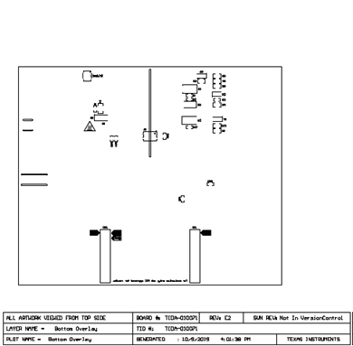
图17.参考设计TIDA-010071 PCB设计图(6)
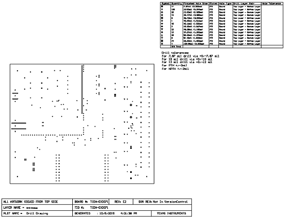
图18.参考设计TIDA-010071 PCB设计图(7)
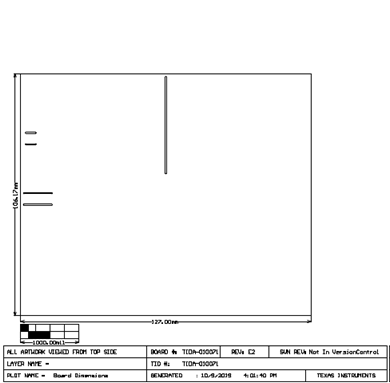
图19.参考设计TIDA-010071 PCB设计图(8)
详情请见:
http://www.ti.com/lit/ug/tiduer6/tiduer6.pdf
和http://www.ti.com/lit/df/tidm249/tidm249.pdf
以及http://www.ti.com/lit/df/tidm250/tidm250.pdf
和http://www.ti.com/lit/df/tidm252/tidm252.pdf
 tidm249.pdf
tidm250.pdf
tidm252.pdf
tiduer6.pdf